As we continue in the 2011 NEC Chapter 3, we are now to the point where we have specialized articles related to specific wiring methods. Here we will depart from covering each article and, instead, cover just the ones which are most commonly seen during the inspections we do most often.
Again, I urge you to please open your codebook and follow along, and then also review the articles that we will be skipping over. You do not have to commit the entire code to memory, although I always admire those who can quote chapter and verse. Just be familiar with what is in the code and, most of all, know where it is or how to look it up. For instance, you should know that we have an article on Integrated Gas Spacer Cable, Article 326. However, I would not bother trying to learn it in detail, mainly due to the fact that in my career I have never seen it installed on a job and have never had to inspect it. So we will not cover these unique portions of the code in these articles.
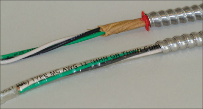
Photo 1. This photo shows Type AC Cable (Art 320) on top with the paper filler, also notice the required insulator has been installed (redhead). The lower example is Type MC Cable (Art 330) which has a Mylar filler that is imprinted with the cable configuration information
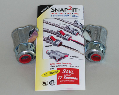
Photo 2. Here is an example of the fittings approved for Types AC and MC Cable, as you can clearly see on the instructions. Please note that these fitting also have an additional insulating throat bushing.
AC cable was first listed as a wiring method in 1899. The UL standard number for AC is UL 4, so you can see it is one of the oldest wiring methods in the industry. It often goes by the nickname of BX, so if you ask an electrician what type of cable assembly he used and he says BX, it is usually AC cable.
AC cable is an assembly that has a steel or aluminum alloy strip wrapped around the conductors in an interlocked configuration that allows for flexibility. Another characteristic you can use to identify it is the paper wrapping around the conductors inside the metal armor. It generally does not include a full size equipment grounding conductor, instead it has a bonding strip in contact with the metal armor. Next, we’ll cover the common items needed to inspect AC cable. First, the bending radius from 320.24 states that the tightest bending radius cannot exceed 5 times the diameter of the cable assembly (on the inner radius). Securing and supporting is covered in 320.20, which states it shall be supported within 12 inches of a termination at a box or other related device, and it shall be supported at intervals not less than 4.5 feet. The one key factor for AC cable is the need for an insulated protection bushing to be used where the conductors emerge from the cable metal sheathing. This is covered in 320.40; what you will usually see in the field is a little red plastic insert that wraps around the conductors to provide this protection, and these are commonly referred to as “redheads” in the field. If you have any further questions about the construction of AC cable, it is covered in 320.100.
Next we are going to jump to Article 330, Metal-Clad Cable: Type MC.
This cable at first glance is similar to Type AC; however, there are some distinct differences, and in today’s world, it is the most common flexible wiring method I have found installed in the last decade. It is made with an aluminum or steel outer strip that is wound into an interlocking sheath to cover the conductors, again resulting in a flexible wiring method. The conductors inside are typically covered with a plastic Mylar, and the equipment grounding conductor is a full-size according to the product standard, UL 1569.
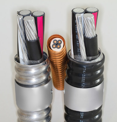
Photo 3. This is an example of different Type MC Cables (Art 330). On the left is a standard feeder MC cable and on the right is a PVC jacketed MC cable approved for exterior, direct burial and concrete encasement. In the center is a fire-rated MC cable. Photo courtesy of General Cable.
In 330.30, the securing and supporting methods are covered. The smaller branch circuit sizes have to be secured within 12 inches of a box or similar item and then must be supported every 6 feet. In the 2014 Code, which we haven’t started using yet for these articles, there is an interesting change for the support of feeder size MC cable installed in vertical runs. The support distances have been increased to every 10 feet for certain conductor sizes, so you might want to get your 2014 NEC and read about the change.
Unlike AC cable, MC doesn’t require the insulated bushing at the termination points. This is often a wrongly enforced item, since most inspectors got used to seeing the little redhead bushings and kept enforcing this for MC cable in error. Quite often, electricians just go ahead and install the bushings on MC anyway in an effort not to delay projects or run the risk of getting turned down on an inspection.
The bending radius of MC cable is found in 330.24, which states the inner radius shall not be less than seven times the diameter of the cable assembly. One note of caution related to branch-circuit MC cable, there are several configurations of MC that have different configurations related to the equipment grounding conductor in the assembly. Some are inside the Mylar wrap; some, outside the wrap. So the issue here is you have to review the installation requirements for each type of MC cable; some have instructions which use certain connectors and terminate the grounding conductor in unique ways. Generally, you will find the manufacturer’s installation requirements attached to the coil of the MC cable. So review a few of these until you get used to and can recognize the proper installation requirements for MC cable.
The one thing you have to look for when inspecting both AC and MC cable assemblies is proper terminations into the connectors. Make sure the connectors are listed for the exact cable being used and have been installed properly so as not to cause any damage to the cable. Also, make sure you look for any places where the cable may have been snagged or caught on a framing member causing the outside armor to separate and expose the conductors. If you find these conditions, no amount of tape can repair it; just replace that run of the installation.
Article 332 deals with Mineral Insulated Metal Sheathed Cable: Type MI.
This is a cable assembly that looks just like copper pipe to the untrained eye; this is because the outer jacket or layer of the assembly is simply copper tubing. Inside, you will find a white compressed material that is around the solid bare conductor providing the insulation. The outer tubing is the equipment grounding conductor. This comes in a multi-conductor assembly; however, it is more commonly installed as a single conductor per cable. Due to its unique design and construction, this cable has a fire rating associated with it, so you will normally see it run for emergency circuits.
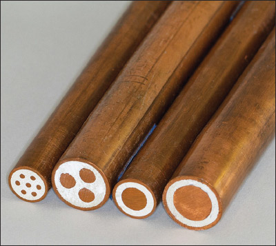
Photo 4. These are four different configurations of Mineral Insulated Cable (Art 332). On the left is a 7 conductor 14 AWG, next is a 3 conductor 4 AWG, followed by a single 1/0 AWG, and on the right is a single 250 kcmil conductor.
One word of caution with MI cable is that you have to install it exactly as directed in the manufacturer’s instructions. If you are using the individual cable assemblies for each phase and the neutral, the factory instructions prefer you to cut out a portion of your panelboard cabinet and to terminate these cables into a brass plate installed over the opening you have cut out; this will prevent inductive heating. Also, the termination process requires an adaption process to get to a stranded conductor that is compatible with circuit breakers, etc. If you come onto a job using MI cable, I suggest you get a copy of the installation instructions and brush up on all these details before you sign off on the inspection.
Nonmetallic-Sheathed Cable: Type NM, NMC, and NMS
Residential work is generally performed using the next wiring method we will cover. Nonmetallic-Sheathed Cable: Type NM, NMC, and NMS are covered in Article 334. As you can tell from the title of this article, this is a cable assembly that has an outer sheathing made of a non-metallic (basically plastic-type) outer covering. Again, please read the uses permitted in 334.10 and the uses not permitted in 334.12. Naturally, as you might guess because of the non-metallic outer sheath, it is a little more subject to damage than metallic type wiring methods; and as such, we need to take a closer look when this wiring method is used. Type NM cable is often used in wood framed construction, and we absolutely want to make sure we don’t have any damaged cable which could lead to an ignition point within the wood structure. I would instruct my inspectors to visually trace each run of NM cable in each room as they entered it during the rough inspection to look for damage.
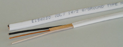
Photo 5. Nonmetallic-sheathed cable (Art 334) is pictured here; notice the paper wrap of the grounding conductor, and legend on the outer jacket.
One of the key uses not permitted is where it will be in a wet or damp location. Please look back in Article 100 under location to see the specific conditions for wet and damp locations. Often a question is raised related to NM cable being used in residential construction and the fact that it might be subject to moisture during construction if it rains. In my jurisdiction, we never worried about this as in the definition of damp location it states “subject to saturation,” and we make the call that although the cable installed threaded through the framing members might get wet for a short period of time, it was not exposed long enough to qualify as saturation. Also, the definition of a dry location states that “A location classified as dry may be temporarily subject to dampness or wetness, as in the case of a building under construction.” However, please remember that any conduits run outside or underground are considered wet locations and, therefore, NM cable is not permitted to be used in these locations. NM cable is required to have a full size equipment grounding conductor.
Please review 334.15 and 334.17, as these are probably the most important things we need to enforce when using NM. These rules cover protection from physical damage. As I mentioned before, in wood framing we have various opportunities for damage from nails, screws, sharp edges of metal gang nails, duct work and more.
In 334.17, it references to 300.4 for protection which, as we should remember, requires that bored holes be at least 1-¼ inches from the face of framing members. Why 1-¼ inches? Well, if you are a combination inspector, you will recall that the penetration distance for the proper attachment of wall coverings is generally ⅞ of an inch. So if we stay 1-¼ inches back, we should be good. If we don’t get the proper distance, then we have to provide what is commonly known as nail plates to protect the cable as per 300.4.
The bending radius of NM cable shall not be less than five times the diameter of the cable assembly. Now I know you are thinking that some NM cable is a modified oval shape and, in those cases, the diameter would be the widest dimension. Again, in 334.30 we find the securing and supporting requirements, which require securement within 12 inches of a termination location and then supported at intervals not to exceed 4-½ feet.
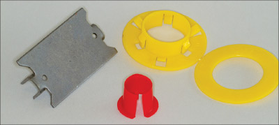
Photo 6. This is an example of the protection items required for various wiring methods. On the left is a nail plate to protect NM cable in wood construction when we don’t get the 1 ¼ “ required clearance. On the right is a bushing used when installing NM cable in metal studs. In the foreground is a larger example of the “redhead” bushing required for Type AC Cable.
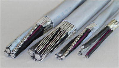
Photo 7. These are Service-Entrance Cables (Art 338). Second from the left is an SEU configuration with a concentrically applied bare conductor. The other three are SER cables with various wire size and configurations.
I have not talked about the ampacities of any of the cables mentioned so far. However, ampacity is generally covered in each article’s 3XX.80. I mention it now because NM cable is basically limited to the 60 degree C column of Table 310.15(B)(16); this is due to the limitations of the connections of the branch-circuit devices. However, you can use the higher ampacity of the conductor insulation for temperature correction and adjustment factors as long as the final calculated ampacity does not exceed the 60 degree C column.
We will continue with Article 338 Service-Entrance Cable: Type SE and USE.
Please review 338.2 for the definitions of SE and USE. As you can see, USE is basically used for underground installations; and if you refer to the uses permitted and uses not permitted, you will find that USE is not allowed to be used for interior wiring. Again, you need to review the code for the specific applications for each of these cable assemblies.
Article 338 is really a small article because of the similarities in many ways of SE cable to NM cable. Several of the installation methods for securing and supporting simply refer you to Article 334. However, please note that SE cable is made to a completely different UL Standard and does not have the same limitations for ampacities. It has different construction requirements, including a flame-retardant, moisture-resistant covering. It can be used for sub-panel feeds, appliance feeds, or for any larger ampacity loads, in addition to its traditional use for outside service-entrance conductors.
The last wiring method we will cover is Article 340 Underground Feeder and Branch-Circuit Cable: Type UF.
It is a unique cable mainly designed to be used underground. This is a good method for wiring inside underground conduits when placed under slabs in residences for feeds to kitchen islands and such. It can also be used for direct burial; therefore, we see it installed outside to feed exterior landscape lighting and other outside equipment. When used underground, it is subject to the requirements of 300.5 for burial depths.
Other than the unique uses permitted and not permitted in 340.10 and 340.12, it is very similar to NM cable and is often confused for NM. The outer sheath has a few different features, including being flame-retardant, moisture-, fungus-, and corrosion-resistant, and being suitable for direct burial in the earth.
This concludes this article; in the next edition, we will tackle the various raceways in the rest of chapter 3. Please remember to use the codebook while reading these articles in order to get the full benefit.




Find Us on Socials